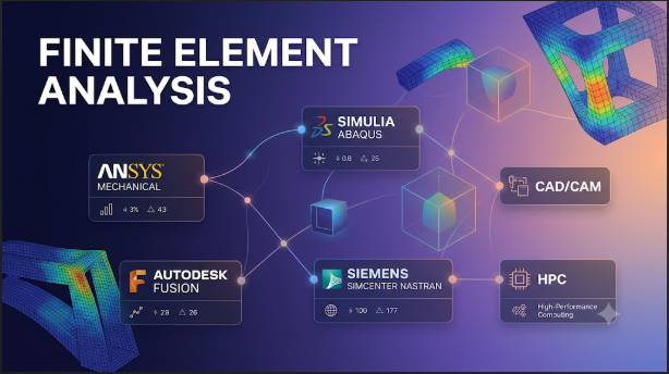
A stress plot can make a weak design look convincing. A smooth animation can make a failed simulation look successful. Neither proves that a part will survive real loads.
Finite Element Analysis (FEA) software helps engineers predict how structures and materials respond to forces, heat, vibration, impact, and other conditions. But different FEA packages use different solver technologies and modeling approaches. A tool that works well for a steel bracket may not suit a rubber seal, a composite aircraft panel, or a medical implant.
The important decision is not simply which package has the most features. It is whether its numerical methods, material models, and analysis types match the physical problem.
This distinction matters to mechanical, automotive, aerospace, civil, energy, and product design teams. It also matters to universities and research groups that need control over their models and methods.
What FEA software actually does
FEA turns a complex physical object into a collection of smaller pieces called elements. These elements connect at points called nodes. Together, they form a mesh.
The software applies material properties, loads, supports, and other conditions to this model. A numerical solver then estimates how the model responds.
For example, an engineer might use FEA to study:
- How much a metal bracket bends under a load.
- Whether a pressure vessel can withstand internal pressure.
- How a machine frame responds to vibration.
- How heat changes stress inside an engine component.
- How a vehicle structure behaves during a crash.
- How a composite panel responds to different loading directions.
- How a rubber seal deforms when compressed.
The results may include stress, strain, displacement, temperature, natural frequency, and reaction forces. The exact results depend on the analysis type and model setup.
FEA is not one single method for every problem. The solver must match the physics.
The first major decision: linear, nonlinear, implicit, or explicit?
Many poor software choices begin with an unclear understanding of the analysis itself. A team may buy a powerful nonlinear solver when its work mainly involves simple linear static analysis. Another team may choose a basic structural package and later discover that it cannot handle its contact or material behavior.
These distinctions help narrow the options.
Linear and nonlinear analysis
Linear analysis assumes a proportional relationship between applied loads and the resulting response. It also relies on simplifying assumptions about geometry and material behavior.
This approach can work well when:
- Deformations remain small.
- Materials stay within their elastic range.
- Contact conditions do not change significantly.
- The structure behaves in a predictable way.
Nonlinear analysis becomes important when these assumptions no longer hold.
Common sources of nonlinearity include:
- Material nonlinearity: Plasticity, rubber-like behavior, creep, or damage changes how a material responds.
- Geometric nonlinearity: Large rotations or deformations change the structure’s stiffness and shape.
- Contact nonlinearity: Parts separate, slide, collide, or press against each other.
A bolted assembly with changing contact conditions may need nonlinear analysis. So may a flexible rubber component that undergoes large deformation.
Nonlinear analysis usually demands more modeling effort and computing time. It also requires more care when interpreting convergence problems.
Implicit and explicit solvers
Implicit and explicit methods solve the equations of motion in different ways.
An implicit solver generally uses iterations to reach equilibrium at each solution step. It often suits static loading, gradual changes, and many structural vibration problems.
An explicit solver advances the solution through small time increments. It is often useful for short, highly dynamic events involving impact, severe contact, or rapid deformation.
The choice is not simply about speed.
A short impact event may suit an explicit solver. A slowly loaded structure with smooth nonlinear behavior may suit an implicit solver. Some difficult contact problems can also make an explicit approach worth evaluating, even when the event itself is not a conventional impact.
Abaqus explains this distinction in its guidance on choosing between implicit and explicit analysis.
FEA software worth evaluating
The following products serve different engineering needs. They are not arranged as a performance ranking. Their value depends on the physics, workflow, and level of control required.
Ansys Mechanical: A broad structural engineering environment
Ansys Mechanical is a commercial FEA environment for structural and related engineering analysis.
Its documented capabilities include linear and nonlinear structural analysis, thermal analysis, vibration, contact, composites, fatigue, acoustics, and coupled-field work. The wider Ansys ecosystem also connects structural simulation with other physics tools.
This makes Mechanical relevant to teams that work across several engineering disciplines. A team might study a component’s thermal response and then examine the stress caused by temperature changes. Another might combine structural analysis with vibration or fatigue work.
Ansys also provides scripting and automation options. Its Mechanical developer documentation describes programmatic model creation, modification, simulation runs, and result access. This can help teams automate repeated design studies.
The main consideration is product scope. Ansys offers different license levels and capabilities. Buyers should confirm that the required contact, nonlinear material, dynamics, and optimization functions sit within their intended package.
Mechanical is worth considering when a team needs a broad structural workflow and may connect it to other engineering simulations. A specialist nonlinear workflow may still justify comparing its setup and solver behavior with Abaqus.
Abaqus: A strong option for complex nonlinear behavior
Abaqus is a finite element analysis product family from Dassault Systèmes. It is particularly relevant when large deformation, complex contact, and advanced material behavior drive the engineering problem.
Its two main general-purpose solvers serve different purposes:
- Abaqus/Standard handles linear and nonlinear analyses using implicit solution methods.
- Abaqus/Explicit handles highly nonlinear transient events using explicit time integration.
These solvers can work together in suitable workflows. For example, an analysis may use one solver for a stage that benefits from implicit methods and another for a stage dominated by rapid nonlinear response.
Abaqus also offers material models for areas such as plasticity, viscoelasticity, and damage. Its contact options have different capabilities and limitations across Standard and Explicit. Engineers should review the actual contact formulation rather than assume that similarly named options behave identically.
Abaqus/CAE provides model creation, job management, and result visualization. Advanced users can also extend workflows through subroutines and scripting.
Abaqus deserves close attention for challenging structural problems. However, its capabilities do not remove the need for suitable material data, contact definitions, and solver expertise. Teams with mostly routine linear work may not need its full nonlinear depth.
Simcenter Nastran: Structural dynamics and established solver workflows
Simcenter Nastran is a structural analysis solver within Siemens’ engineering simulation portfolio.
It supports structural analysis, including linear and multistep nonlinear work. Its capabilities also cover structural dynamics, noise and vibration, rotor dynamics, acoustics, and optimization.
This makes it relevant to engineers who need more than a static stress result. For example, a product may pass a static strength check but still experience unwanted vibration during operation. Modal and frequency-response analysis can help investigate that behavior.
Simcenter Nastran is often considered alongside environments such as Simcenter 3D and Simcenter Femap. These tools support model preparation and engineering workflows around the solver.
The important distinction is that the solver and its surrounding environment are not the same thing. Buyers should identify which application creates the model, which solver runs it, and which licenses cover the required analysis types.
Simcenter Nastran is a useful candidate for teams with established structural dynamics or Nastran-based processes. Teams focused on highly nonlinear impact or unusual material behavior should test those exact cases before choosing it.
Altair OptiStruct: Structural analysis with design optimization
Altair OptiStruct combines structural analysis with design optimization.
Its documented analysis scope includes linear and nonlinear statics, dynamics, vibration, acoustics, fatigue, heat transfer, and multiphysics. It also supports structural optimization methods.
Optimization is an important reason to consider this product. Rather than only asking whether a design meets a stress limit, engineers can define design goals and constraints. They can then explore changes to material distribution, shape, or dimensions.
For example, a team designing a support structure might seek lower mass while maintaining stiffness and other required limits. Topology optimization can help explore where material may be useful or unnecessary.
However, an optimized shape is not automatically ready for manufacturing. Engineers still need to consider minimum wall thickness, tooling, joining, material direction, production methods, and inspection.
OptiStruct is worth evaluating when design exploration and structural optimization are central to the workflow. Buyers should also check how it fits with their existing pre-processing, post-processing, and other Altair tools.
Code_Aster: Open-source structural simulation with research depth
Code_Aster is open-source software developed by EDF’s research and development organization.
It focuses on numerical simulation in structural mechanics and thermodynamics. Its purpose includes studying the behavior of structures and materials, supporting engineering studies, and developing numerical methods.
Code_Aster is not simply a free version of a commercial graphical FEA package. It is a technical simulation environment that may require users to understand its modeling workflow, command structure, and solver behavior.
That can be an advantage for research teams and organizations that need greater control over their analysis process. It can also create a learning and support burden for teams accustomed to integrated commercial interfaces.
Organizations should assess the surrounding workflow too. Model preparation, visualization, automation, documentation, and technical support may involve additional tools or internal expertise.
Code_Aster is a credible option for technically capable teams that value open-source access and control. It may be less suitable for groups that need a highly guided, integrated commercial workflow with vendor-managed support.
FEBio: A specialist choice for biomechanics
FEBio is an open-source nonlinear finite element solver developed for biomechanics and biophysics.
Its focus makes it different from general-purpose structural packages. It supports models relevant to soft tissues and biological materials, including large deformation and complex material behavior. Its wider physics capabilities include mixture mechanics and fluid-solid interaction.
These features matter in research involving tissues, implants, and biological structures. A soft tissue model may need material behavior that differs greatly from ordinary engineering metals.
FEBio Studio provides a graphical environment for creating models, running analyses, and viewing results. The solver itself also supports file-based workflows.
Its specialist focus is both its strength and its boundary. A team studying general machine frames or industrial brackets may gain little from its biomechanics orientation. A research group studying tissue mechanics may find that focus more relevant than a broad industrial package.
How the main options differ
| Software | Main strength | Typical fit | Important consideration |
|---|---|---|---|
| Ansys Mechanical | Broad structural and coupled engineering analysis | Product engineering and multidisciplinary teams | Check license levels and required modules |
| Abaqus | Complex nonlinear behavior and contact | Advanced structural analysis and impact studies | Requires careful solver and model selection |
| Simcenter Nastran | Structural dynamics, vibration, and acoustics | Mechanical, aerospace, and system-level engineering | Confirm solver and pre/post-processing requirements |
| Altair OptiStruct | Structural analysis and optimization | Lightweight design and design exploration | Optimized geometry still needs engineering review |
| Code_Aster | Open-source structural mechanics and thermodynamics | Research and technically capable engineering teams | Requires workflow and support planning |
| FEBio | Nonlinear biomechanics and biological materials | Biomechanics and biophysics research | Specialist scope is not a general industrial FEA replacement |
The model matters more than the color map
A solver can complete a job and still produce a misleading answer. The numerical result only has value when the model represents the real problem closely enough.
Several checks should be part of every serious FEA workflow.
1. Start with the real load path
Loads and supports must represent how the component works.
A bracket attached through bolts should not automatically be modeled as perfectly fixed across its entire mounting face. That assumption may create unrealistic stiffness.
Likewise, a component that transfers force through a contact surface needs an appropriate contact definition. A simplified connection may be acceptable for an early study, but its effect should be understood.
Ask:
- Where does the force enter the structure?
- How does the structure transfer that force?
- Where can it move?
- Which parts can separate or slide?
- Does the model represent the actual support conditions?
A precise mesh cannot repair an unrealistic load path.
2. Choose the correct material model
Material properties strongly affect predicted results.
A simple elastic model may be suitable for a small deformation in a metal part. It may not represent permanent deformation after yielding.
Rubber, foam, plastics, composites, and biological tissues can require more specialized material descriptions. Some materials also behave differently with temperature, loading rate, or direction.
Use measured material data where possible. If test data are unavailable, document the assumptions and examine how sensitive the results are to them.
Do not select a complex material model just because the software offers one. The model needs suitable parameters and a clear physical purpose.
3. Treat the mesh as an engineering decision
The mesh controls how the geometry is divided into elements. Element type, size, shape, and quality can affect the solution.
A very coarse mesh may miss important local behavior. A very fine mesh may consume substantial computing resources without improving the answer in a meaningful way.
Mesh refinement should focus on areas where the solution changes rapidly. These may include holes, contact regions, sharp geometry changes, and stress concentrations.
A mesh convergence study provides stronger evidence than a single attractive result. Run the same model with progressively refined meshes. Then compare the engineering quantities that matter, such as displacement, reaction force, or stress away from singular regions.
NAFEMS guidance on mesh convergence provides useful background on this often overlooked issue.
4. Understand stress singularities
Some idealized models create extremely high stresses near sharp corners, point loads, or perfectly fixed edges.
These may be mathematical singularities rather than realistic material stresses. Refining the mesh can increase the reported peak stress without producing a stable value.
In such cases, engineers should investigate the physical geometry and load transfer. They may need a more realistic radius, contact model, or load distribution.
Do not judge a design only by the highest number shown in a stress plot.
5. Check solver convergence and physical meaning
A completed analysis does not automatically mean that the model is correct.
For nonlinear analysis, the solver may struggle to reach equilibrium. Contact changes, material behavior, large deformation, and poor constraints can all affect convergence.
Review more than the final status. Check residuals, energy behavior where relevant, reaction forces, deformation patterns, and whether the solution makes physical sense.
Also compare results with hand calculations, analytical solutions, test data, or trusted benchmark cases when possible.
Verification and validation are not the same
These two terms are often used together, but they answer different questions.
Verification asks whether the equations were solved correctly. It includes checking numerical implementation, solution behavior, and whether results converge as the mesh or solution settings change.
Validation asks whether the model represents the real physical system well enough. It involves comparing predictions with experiments or other reliable evidence.
A solver may pass numerical verification and still produce poor predictions if the material data or boundary conditions are wrong.
The Abaqus Verification Guide describes test cases that compare software results with independent solutions or experimental results. Such documentation is useful, but it does not validate every model a user creates.
For high-risk engineering work, validation should be planned as part of the project rather than added after the simulation is complete.
What does FEA software really cost?
Software purchase or subscription fees are only one part of the total cost.
The final expense may also include:
- Advanced solver modules.
- Additional user or floating licenses.
- High-performance computing capacity.
- Cloud compute or storage charges.
- CAD and pre-processing integrations.
- Training and technical support.
- Model management and collaboration systems.
- Time spent building and checking models.
- Maintenance of scripts and custom workflows.
Commercial vendors may use different licensing structures. Some separate capabilities into product levels or add-on modules. Others connect solver access to broader software suites or computing entitlements.
Open-source software can reduce license costs, but it does not remove the cost of engineering time. Teams still need people who understand the solver, model setup, debugging, automation, and result review.
A low-cost license can become expensive if it creates a long setup process or cannot handle the required analysis. A more expensive package may be justified when it fits an established workflow and reduces repeated engineering effort.
Ask vendors for a complete cost breakdown using the actual analysis types and computing needs of your team.
How to evaluate software before committing
A polished product demonstration is not enough. Vendors usually show workflows that suit their software. Your team needs to know how it handles your difficult cases.
A useful pilot should include a small set of representative models:
- A routine model: Use a familiar component with a known load case.
- A demanding model: Include the contact, material, or geometric nonlinearity that creates difficulty in your work.
- A validation model: Use a case with reliable experimental or analytical reference data.
Then assess the results against the same engineering requirements.
Compare the workflow, not just the solver result
During the pilot, examine:
- How easily the team can import and update CAD geometry.
- Whether the mesh supports the required element types.
- How the software defines contacts and connections.
- Whether the needed material models are available.
- How it handles failed or difficult solution steps.
- Whether engineers can automate repeated tasks.
- How results can be reviewed and shared.
- Whether models can move between the software and existing tools.
- How much computing capacity each analysis needs.
A solver may produce a similar result to another package but require more effort to prepare the model. That difference can matter greatly in a team that runs many design iterations.
Ask vendors these specific questions
- Which solver handles our most demanding analysis?
- Are the required material models included in the proposed license?
- Which contact formulations are available?
- Can the software handle our expected model size?
- What computing resources do the solver and workflow require?
- Can we automate model creation and result extraction?
- What happens when a model fails to converge?
- Can we access input files and results outside the vendor’s environment?
- What training and technical support are included?
- How are license use and compute charges calculated?
Ask for written answers where license scope, technical limits, or deployment conditions affect the purchase.
Deployment, data, and regional support
FEA models often contain sensitive product designs, supplier information, and engineering data. Deployment choices therefore matter.
Some organizations prefer local workstations or on-premises computing. Others use remote computing or cloud services for larger workloads. The right approach depends on data rules, network access, IT policy, and the available computing environment.
Before choosing a deployment model, check:
- Where model files and simulation results are stored.
- Who can access project data.
- How backups and retention work.
- Whether the software supports your organization’s identity controls.
- How data moves between local systems and remote computing.
- Whether supplier or customer agreements restrict data hosting.
- Which export or industry rules apply to your work.
Regional support also deserves attention. In India and other markets, buyers should check local training, distributor expertise, support hours, payment terms, and access to suitable computing resources. A strong solver with no practical support path can create avoidable delays.
Do not assume that every feature, license, or support arrangement is available in every region. Confirm the terms with the vendor or authorized reseller.
When a simpler method is better
FEA is not necessary for every engineering question.
A hand calculation may be enough for a simple beam, basic stress estimate, or early sizing decision. A standard engineering formula can be faster and easier to review.
FEA becomes more valuable when geometry, load paths, material behavior, contact, or boundary conditions make simple calculations insufficient.
Even then, simulation should not automatically replace physical testing. Tests remain important when failure has serious consequences or when material and operating conditions are uncertain.
A sensible workflow often combines hand calculations, simulation, engineering review, and physical tests. Each method checks the others.
Choose the software around the hardest model you must trust
The best FEA choice depends on the most demanding analysis your team needs to perform reliably.
Ansys Mechanical offers a broad structural environment. Abaqus deserves attention for complex nonlinear behavior and contact. Simcenter Nastran is relevant to structural dynamics and vibration workflows. OptiStruct brings structural analysis together with design optimization. Code_Aster offers an open-source route for structural mechanics, while FEBio serves specialist biomechanics research.
Before buying, define the physics, material behavior, contact conditions, and required outputs. Test those cases with real engineering data. Check mesh convergence and compare predictions with independent evidence.
Choose the package that helps your team build, solve, and validate the right model—not the one that produces the most impressive simulation image.







Leave a Reply
You must be logged in to post a comment.