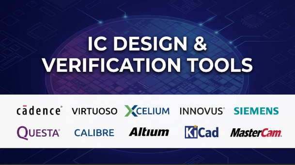
A chip can pass thousands of tests and still contain a serious design flaw. A timing path may fail after layout. A reset sequence may break under an unusual condition. A small logic change may affect an unrelated block.
These risks make integrated circuit (IC) design more than a coding task. Engineers must describe the hardware, test its behavior, prove important properties, and prepare it for manufacturing.
IC design and verification tools support this work at different stages. Some simulate digital logic. Others check mathematical properties, create physical layouts, or verify manufacturing rules. The challenge is choosing tools that work together without leaving gaps between design stages.
The right choice depends on the chip, the design team, and the level of evidence required before tape-out.
The work does not happen in one tool
Most digital IC projects begin with a hardware description. Engineers write register-transfer-level (RTL) code using languages such as Verilog, SystemVerilog, or VHDL.
RTL describes how a digital circuit behaves across clock cycles. It does not, by itself, define the final physical layout.
A typical design flow moves through several connected stages:
- Design entry: Engineers write RTL or use higher-level design methods.
- Simulation: Testbenches exercise the design under different conditions.
- Formal verification: Mathematical methods check properties across possible input and state conditions.
- Logic synthesis: Tools convert RTL into a gate-level netlist.
- Physical design: Engineers place cells, build clock networks, and route connections.
- Timing and physical checks: Tools examine delay, power, signal integrity, and layout rules.
- Sign-off: The team reviews required checks before sending the design for fabrication.
These stages do not form a simple one-way pipeline. Engineers often return to earlier work after finding a problem.
For example, a timing failure may require changes to RTL, constraints, synthesis settings, or physical placement. A formal failure may reveal a design bug or an incorrect verification assumption.
The tools must therefore exchange reliable data throughout the project.
First, understand the difference between verification methods
The word verification covers several different activities. Treating them as interchangeable can lead to expensive gaps.
Simulation checks selected scenarios
Simulation runs a design with test inputs. Engineers observe outputs and compare them with expected behavior.
A testbench can check reset behavior, bus transactions, memory access, and error handling. SystemVerilog and UVM are common parts of larger verification environments.
Simulation is flexible and useful for debugging. But it only explores the scenarios that the tests actually run.
A passing test suite does not prove that every possible input sequence works.
Formal verification checks stated properties
Formal tools use mathematical methods to check whether a design satisfies defined properties.
They can examine many possible input and state combinations without relying on a manually selected test sequence.
This makes formal methods useful for checking control logic, protocols, state machines, and design equivalence.
However, formal verification depends on sound properties and assumptions. A property that describes the wrong behavior can still produce a misleading result.
Emulation runs designs on hardware platforms
Hardware emulation maps a design onto a specialized hardware system. This can run complex chip models faster than software simulation.
It helps teams test large systems, run long workloads, and start software development before physical chips exist.
Emulation is especially useful when software, firmware, and hardware must work together.
FPGA prototyping supports early software work
FPGA prototypes implement a design using programmable hardware. They can support early software development and system testing.
They are not the same as the final chip. FPGA resources, timing, and interfaces differ from the target silicon.
A prototype can expose system-level problems, but it cannot replace all silicon sign-off checks.
Physical verification checks the layout
Physical verification examines the chip layout against design and manufacturing rules.
Design-rule checking (DRC) finds layout violations. Layout-versus-schematic (LVS) checks whether the physical layout matches the intended circuit.
These checks address different risks from RTL simulation and formal verification. A design can pass functional tests and still fail physical verification.
Commercial IC design platforms: three major ecosystems
Commercial IC design tools often come as connected product families. Each family covers several parts of the design and verification process.
The three major suppliers offer broad portfolios. Their products overlap, but their workflows and strengths differ.
Cadence: connected design implementation and verification
Cadence offers tools for RTL simulation, formal verification, synthesis, physical implementation, and sign-off.
Its verification portfolio includes Xcelium Logic Simulation and the Jasper Formal and Static Verification Platform.
Xcelium supports logic simulation for complex digital designs. It fits teams that need a commercial simulation environment within a wider verification flow. Jasper addresses a different problem. It uses formal methods to check properties, connectivity, low-power behavior, and other design conditions.
For physical implementation, Innovus+ combines RTL synthesis, floorplanning, placement, routing, and optimization. Tempus handles static timing analysis and timing sign-off. These tools can share design data and support connected implementation workflows.
This integration can help teams reduce handoff friction. It can also make a single-vendor environment attractive when the organization already uses Cadence tools.
But a connected portfolio does not remove the need for independent checks. Teams should still compare results, validate constraints, and confirm support for their target process.
Synopsys: simulation, formal proof, and physical design
Synopsys has a broad portfolio spanning design, verification, implementation, and sign-off.
VCS is its functional simulation platform. It supports SystemVerilog-based verification, coverage analysis, and integration with the Verdi debug environment. This makes it relevant to teams running large simulation regressions.
VC Formal provides formal verification. Its applications cover areas such as control logic, datapaths, low-power behavior, and verification coverage analysis. It can also help teams investigate whether uncovered coverage points are unreachable.
For physical implementation, Fusion Compiler and IC Compiler II address synthesis and place-and-route workflows. PrimeTime is widely used for static timing analysis and sign-off.
The key consideration is how these products fit the team’s existing flow. A simulator, formal engine, implementation tool, and timing engine must agree on design versions, constraints, libraries, and handoff data.
Synopsys also offers ZeBu emulation and HAPS prototyping. These platforms support hardware-assisted verification and early software development. They become more relevant as designs grow into complex systems-on-chip.
Siemens: verification depth and physical sign-off
Siemens EDA covers IC design, verification, physical implementation, and manufacturing checks.
Its Questa One portfolio brings together simulation, formal, and static verification technologies. It is aimed at teams that need to manage verification across large designs and complex architectures.
Siemens also offers Veloce for hardware-assisted verification. The platform includes emulation and FPGA prototyping capabilities. This helps teams test hardware and software together before silicon becomes available.
For physical verification, Calibre is a major part of the portfolio. It supports physical verification and design-for-manufacturing workflows. These checks matter because a functionally correct design may still violate manufacturing rules.
Siemens also offers Aprisa for digital physical implementation and mPower for power integrity analysis.
This portfolio is worth examining when physical verification and manufacturing sign-off carry major weight. Buyers should check which Calibre, Questa, and implementation products their flow requires. Product names alone do not establish that every capability comes in one package.
Open-source tools can cover more than early learning
Open-source IC tools have grown beyond simple demonstrations. They now support simulation, synthesis, formal checks, and parts of physical implementation.
However, an open-source flow is not automatically equivalent to a commercial production flow. Process support, tool maturity, foundry data, and sign-off requirements still matter.
Verilator: compiled RTL simulation
Verilator converts Verilog and supported SystemVerilog designs into C++ or SystemC models.
This compiler-based approach can work well for fast simulation and software-driven verification. Teams can connect it to C++ test environments or Python-based frameworks.
But Verilator is not a traditional event-driven simulator. Its supported language features and simulation behavior differ from commercial simulators.
Check the language constructs, timing behavior, and verification features your design needs before choosing it as the main simulator.
cocotb: Python-based testbenches
cocotb lets engineers write hardware verification tests in Python.
It connects Python testbenches to supported HDL simulators. Engineers can create drivers, monitors, scoreboards, and test sequences without writing every test in SystemVerilog.
This can suit teams with strong Python skills or projects that benefit from software-style test automation.
cocotb is a verification framework, not a simulator. It still needs a compatible simulator underneath it.
Yosys: open-source logic synthesis
Yosys is an open-source synthesis framework. It reads supported RTL and transforms it into logic representations and mapped netlists.
It is useful for research, education, prototyping, and custom hardware flows. Its ecosystem also connects with other open-source tools.
Yosys does not provide a complete physical design environment by itself. Teams need additional tools for placement, routing, timing analysis, and physical checks.
Its support for language features and target libraries must also match the design.
OpenROAD: physical implementation
OpenROAD provides an open-source digital implementation toolchain. Its flow covers steps such as floorplanning, placement, clock-tree synthesis, routing, and design finishing.
The project supports research and practical design exploration. It also gives engineers more visibility into the implementation process than closed tools may allow.
OpenROAD is especially useful when teams want to study physical design or build custom flows. Its results depend on the platform configuration, process data, constraints, and design.
Do not assume that a successful open-source run proves foundry-ready sign-off. Confirm the exact process design kit, rule decks, and required verification flow.
A note about OpenLane
OpenLane helped make open RTL-to-GDS workflows more accessible. However, its original repository now directs new projects toward LibreLane.
That distinction matters when selecting a maintained flow. Teams should review the current project guidance rather than starting from an older tutorial without checking its status.
How the main options compare
| Tool or ecosystem | Main role | Strong reason to consider it | Important consideration |
|---|---|---|---|
| Cadence Xcelium and Jasper | Simulation and formal verification | Connected verification portfolio | Check product and application licensing |
| Cadence Innovus+ and Tempus | Implementation and timing sign-off | Integrated digital design workflow | Verify process and sign-off support |
| Synopsys VCS and VC Formal | Simulation and formal verification | Broad verification and debug ecosystem | Plan for constraints and tool integration |
| Synopsys Fusion Compiler and PrimeTime | Physical implementation and timing | Connected implementation and sign-off flow | Validate foundry and library support |
| Siemens Questa One | Simulation, formal, and static verification | Broad verification portfolio | Confirm required product configuration |
| Siemens Calibre and Aprisa | Physical verification and implementation | Strong focus on layout checks and implementation | Confirm foundry-qualified rule support |
| Verilator and cocotb | Simulation and Python verification | Open workflows and software-driven tests | Check language and simulator compatibility |
| Yosys and OpenROAD | Synthesis and physical implementation | Open RTL-to-layout experimentation | Production sign-off needs separate validation |
These options are not direct substitutes in every case. Some handle simulation, while others create layouts or verify manufacturing rules.
A sensible comparison starts with the stage that causes the greatest risk or delay.
The most important buying decision is the verification strategy
A common mistake is choosing a simulator first and treating it as the whole verification plan.
Simulation matters, but complex chips need several kinds of evidence. A strong strategy combines methods that catch different classes of problems.
Consider a chip with multiple clock domains, low-power states, and a complex bus interface.
Simulation can exercise normal traffic and error cases. Formal verification can check protocol properties and state transitions. Clock-domain crossing analysis can identify unsafe signal transfers. Emulation can run longer system workloads. Physical verification can check the final layout.
Each method answers a different question.
Match each risk to the right method
| Design risk | Useful method | What it helps establish |
|---|---|---|
| Incorrect output for a tested input sequence | RTL simulation | Expected behavior for executed tests |
| Rare control-state or protocol bug | Formal verification | Whether stated properties hold under defined assumptions |
| Unsafe clock-domain transfer | CDC analysis | Whether signals cross clock domains safely |
| Reset or power-state issue | Simulation and formal low-power checks | Whether defined power and reset behavior is correct |
| Hardware and firmware interaction problem | Emulation or FPGA prototyping | Whether software and hardware work together |
| Timing failure after placement and routing | Static timing analysis | Whether paths meet defined timing constraints |
| Layout rule violation | DRC and LVS | Whether the layout meets rules and matches the intended circuit |
The exact flow depends on the chip’s architecture and process.
No single method proves every property. The team must define what evidence it needs before tape-out.
What matters when selecting an IC toolchain
A product demonstration can make almost any tool look capable. The real test is whether it works with your design, libraries, process, and engineering workflow.
1. Language and design support
Start with the hardware description languages used by the team.
Check support for the required Verilog, SystemVerilog, VHDL, SystemC, and mixed-language features. Also check assertions, constrained-random testing, coverage, and relevant verification standards.
Do not rely on a broad claim such as “SystemVerilog support.” Ask which language constructs and verification features the tool supports.
2. Foundry and process compatibility
This is one of the most important checks for physical design.
A tool may support advanced physical implementation in general. That does not mean it supports every foundry process or process design kit.
Ask whether the exact tool version supports your intended process. Confirm access to required libraries, technology files, extraction settings, and physical verification decks.
For a production design, foundry qualification and the approved sign-off flow matter more than a feature list.
3. Timing and power analysis
Power, performance, and area are connected.
A design may meet its timing target but consume too much power. Another may meet power limits but fail timing after routing.
Check how the flow handles:
- Multi-mode and multi-corner timing analysis
- Parasitic extraction
- Signal integrity and crosstalk
- Static and dynamic power
- IR drop and electromigration
- Timing constraints and exceptions
The team should also understand which results are estimates and which are accepted for sign-off.
4. Debug and coverage closure
A simulator that runs tests quickly can still create a difficult debug process.
Review waveform navigation, failure tracing, regression management, coverage analysis, and testbench quality checks.
Ask how the tool helps engineers identify the cause of a failure. Also ask how it tracks unresolved coverage goals.
Coverage numbers alone do not prove that a design is correct. Teams need to understand what the tests and properties actually cover.
5. Integration and data exchange
A toolchain often includes products from several vendors.
That makes file formats, database access, scripting, and handoff quality important.
Check support for formats such as Liberty, LEF/DEF, SDC, SPEF, and relevant netlist formats. The exact formats depend on the design stage.
Also check whether tools preserve constraints, hierarchy, naming, and design intent during handoffs.
A broken handoff can create errors that look like design problems.
6. Compute and infrastructure costs
IC tools can require substantial computing resources.
Large simulation regressions may need many CPU cores and significant memory. Formal verification can demand considerable compute for difficult proofs. Emulation requires specialized hardware and supporting infrastructure.
The software license is only one part of the cost.
Include compute, storage, infrastructure, maintenance, training, support, and engineering time in the total cost estimate.
7. Licensing, security, and data control
Commercial EDA licenses may use named-user, floating, token, or other arrangements. Exact terms vary by product and contract.
Ask how licenses work across local machines, remote servers, and cloud environments. Confirm whether the team can run parallel jobs without creating license bottlenecks.
Also examine access controls, project data handling, remote support, and restrictions on moving design files.
Chip designs can contain valuable intellectual property. Security reviews should cover the complete tool environment, not just the vendor’s website.
Why open-source and commercial tools often work best together
Open-source tools can reduce entry costs and give teams control over parts of their flow. They also help universities, researchers, and startups understand how synthesis and physical design work.
Commercial tools offer broader product portfolios and established support for many advanced design workflows. They may also provide foundry-qualified capabilities and specialized verification features.
The two approaches can complement each other.
For example, a research team may use Verilator and cocotb for early RTL testing. It may use Yosys to explore synthesis and OpenROAD to study physical implementation.
A commercial flow may still be needed for production sign-off, depending on the foundry and project requirements.
The key is to define which results are exploratory and which results are accepted as final evidence.
Questions to ask before buying
A useful vendor evaluation should include real design material, not just prepared demonstrations.
Ask each vendor:
- Does the tool support our exact HDL features and verification methodology?
- Which foundries and process nodes support our required flow?
- Which checks are included, and which need separate products?
- Can we reuse existing testbenches, assertions, scripts, and constraints?
- How does the tool connect with our current simulators and implementation tools?
- What happens when a design fails formal proof or timing closure?
- Can we reproduce results across machines and software versions?
- How are licenses shared across teams and compute environments?
- What support is available for our region and project schedule?
- Which outputs are accepted by our foundry for final sign-off?
A pilot should use a representative block from the actual design. It should include realistic constraints, libraries, test cases, and expected outputs.
Measure more than runtime. Track debug effort, proof completion, coverage quality, timing convergence, and handoff reliability.
A practical way to choose
The right toolchain depends on the work your team needs to complete.
- For university courses and learning: Start with Verilator, cocotb, Yosys, and OpenROAD. They provide a practical way to explore digital design workflows.
- For RTL verification teams: Compare VCS, Xcelium, and Questa One against your language, testbench, regression, and debug needs.
- For formal verification teams: Evaluate Jasper, VC Formal, and Questa formal products against the properties and proof problems you need to solve.
- For advanced digital implementation: Compare Innovus+, Fusion Compiler, and Aprisa using the target process, constraints, and physical design workload.
- For physical sign-off: Examine Calibre and the relevant timing, extraction, and power sign-off tools required by your foundry flow.
- For large SoC software development: Consider Palladium, ZeBu, Veloce, and their related prototyping platforms.
Do not select an entire portfolio just because one product performs well. Evaluate each critical stage and the handoffs between them.
The most reliable IC toolchain is not necessarily the one with the most features. It is the one that gives engineers clear, repeatable evidence at every important stage—from RTL behavior to physical sign-off.




Leave a Reply
You must be logged in to post a comment.